CNC milling & PCB
GRBL Server isn't laser-only. Every job carries a tool type — laser, spindle, or drag — and the engines emit the right G-code for whatever is mounted on the machine: power modulation for lasers, Z plunges and retracts for rotating and dragging tools. On top of that sit two PCB-specific formats (Excellon drill files and Gerber copper layers), surface leveling for never-quite-flat stock, and a 3D preview for any program that moves in Z.
Tool types: laser, spindle, drag
The Tool type selector sits at the top of the engine parameters — in an interface's Engine Params dialog and in Manual mode on the Set up job page:
- laser — a power-modulated beam. No Z motion; engagement is the laser-on command (M3/M4 + S power). This is the default, and the behaviour of every job saved before tool support existed.
- spindle — a router or mill bit cutting at depth. The spindle starts once at program start (
M3 S<rpm>, with an optional spin-up dwell) and runs for the whole program; engagement is a Z plunge to the pass depth at the plunge feed, disengagement is a rapid retract to the safe height. - drag — a diamond-drag / scratch engraver: identical Z motion to the spindle, but with no spindle commands at all (the tip is passive).
The settings panel adapts to the tool: laser power fields appear only for laser jobs, the cutting-depth and spindle group only for spindle/drag jobs. Switching tool type back and forth never loses values — hidden fields keep what you entered.
Machining operations & holding tabs
A laser follows the drawn line with negligible kerf; a physical cutter has a diameter, so following the line would make every part too small by a tool radius. The Operation setting (spindle/drag jobs) decides what the tool does with the geometry:
| Operation | What it does |
|---|---|
engrave | Follow the geometry as drawn — the default, and the right choice for marking and V-carving lines. |
cut_outside | Offset every closed ring outward by the tool radius. The piece inside survives at exactly the drawn size — profile cuts, board cut-outs. |
cut_inside | Offset inward. The hole ends up at the drawn size — windows, slots, pocket walls. |
pocket | Clear the interior of closed shapes: the boundary is inset by the tool radius, the inside is filled line by line at the configured stepover, and a finishing pass runs along the inset boundary. |
Rings combine by the even-odd rule, so a ring drawn inside another ring is treated as a hole — pocket around it, cut inside it, exactly as you'd expect.
Holding tabs
On cut_outside / cut_inside operations you can leave small bridges uncut so the part doesn't break loose and shift on the final pass. Set the number of tabs per contour, their width along the contour, and their height (material left under each tab, measured up from the final cut depth). The tabs only affect the deepest passes — earlier passes cut straight through.
Depth & spindle parameters
The Cutting depth & spindle group appears for spindle and drag tools:
| Parameter | Default | What it does |
|---|---|---|
| Operation | engrave | See above. |
| Tool diameter | 3.175 mm | Cutter diameter — used to offset contours and space pocket passes. |
| Pocket stepover | 40 % | Distance between pocket clearing lines, as a percentage of the tool diameter. |
| Holding tabs / width / height | 0 / 4 mm / 1 mm | Bridges left uncut on cut operations. 0 disables tabs. |
| Cut depth | 1 mm | Final depth below the material surface. |
| Depth per pass | 0.5 mm | Maximum material removed per pass; the program steps down until the cut depth is reached. 0 cuts the full depth in one pass. |
| Safe Z height | 5 mm | Height above the material for travel moves between cuts. |
| Plunge feed | 100 mm/min | Feed rate for vertical plunges into the material. |
| Spindle speed | 10000 RPM | The S word of the M3 issued at program start (spindle tool only). |
| Spin-up delay | 0 s | Dwell after starting the spindle so it reaches speed before cutting. |
Drill files (Excellon)
Drop a .drl or .xln file — the drill format every EDA package exports — into any file source and set it up like any other job. The engine converts the hole list into a drilling program:
- Holes are grouped by drill size, in file order.
- Each hole is peck-drilled: the bit feeds down depth per pass at a time, fully retracting to the safe height between pecks to clear chips, until it reaches the cut depth.
- Between size groups the spindle stops and the program pauses (
M0) with a comment telling you which bit to fit — change the bit, hit resume, and the spindle restarts.
Drill jobs require the spindle tool type — laser and drag jobs are rejected with a clear error.
PCB isolation routing (Gerber)
Load a Gerber copper layer (.gbr, .ger, or the Protel-style .gtl / .gbl) exported from KiCad, Eagle, Altium, EasyEDA or any other EDA package. GRBL Server parses the copper geometry and generates isolation toolpaths: the cutter follows outward offsets of the copper, cutting a groove around every pad and trace to electrically isolate the nets.
- Isolation passes — each extra pass steps outward by half the tool diameter, widening the cleared channel.
- Extra clearance — additional gap between the copper edge and the first cut, on top of the tool radius.
- Depth, pecking passes, safe-Z travel and feeds behave exactly like every other spindle job.
Isolation milling needs a rotating V-bit or end mill, so the spindle tool type is required here too.
Surface leveling
PCB isolation cuts about 0.1 mm into copper that is 0.035 mm thick — while a real board sits 0.1–0.3 mm un-flat across its width. A fixed Z0 either misses the copper or ploughs through it. Surface leveling fixes this by probing the actual surface and warping the program to follow it.
Before you start
- Wire the bit as the probe input and attach the probe clip to the copper (the probe works with conductive surfaces).
- Jog to the front-left corner of the job and zero Z on the surface there — that point is the reference the heightmap is measured against.
Probing and applying
- Open the job in the Job station. For jobs with Z motion, a Surface leveling button appears next to the preview controls.
- Set the grid spacing (default 7.5 mm), an optional margin, the safe Z for hops between points, the max probe depth and the probe feed. The dialog shows the planned grid size before you commit.
- Click Start probing. The machine probes each grid point with
G38.2, serpentine row by row, with live progress. You can abort at any time. - When the grid completes, the heightmap is saved on the job and the program is swapped for a leveled copy: every cutting move's Z is shifted by the surface deviation at its XY position, and long moves are subdivided so the tool tracks the surface between grid points.
Remove leveling (in the same dialog) points the job back at the original, unwarped program — the probed map is kept, so you can re-apply it. If you regenerate a leveled job, the warp is automatically re-applied from the stored heightmap.
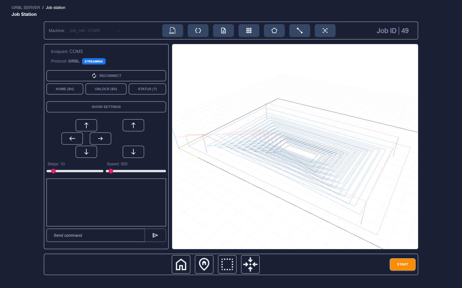
The 3D preview
Programs that actually move in Z — CNC milling, drag engraving, drilling, any pass-through file with Z motion — get a 3D preview in the Job station instead of the flat canvas: an orbitable view with the machine's grid on the Z0 (material-top) plane, travel moves in red, and cutting moves shaded by depth (light = shallow, dark = deep). Laser jobs keep the fast 2D preview, shaded by power.